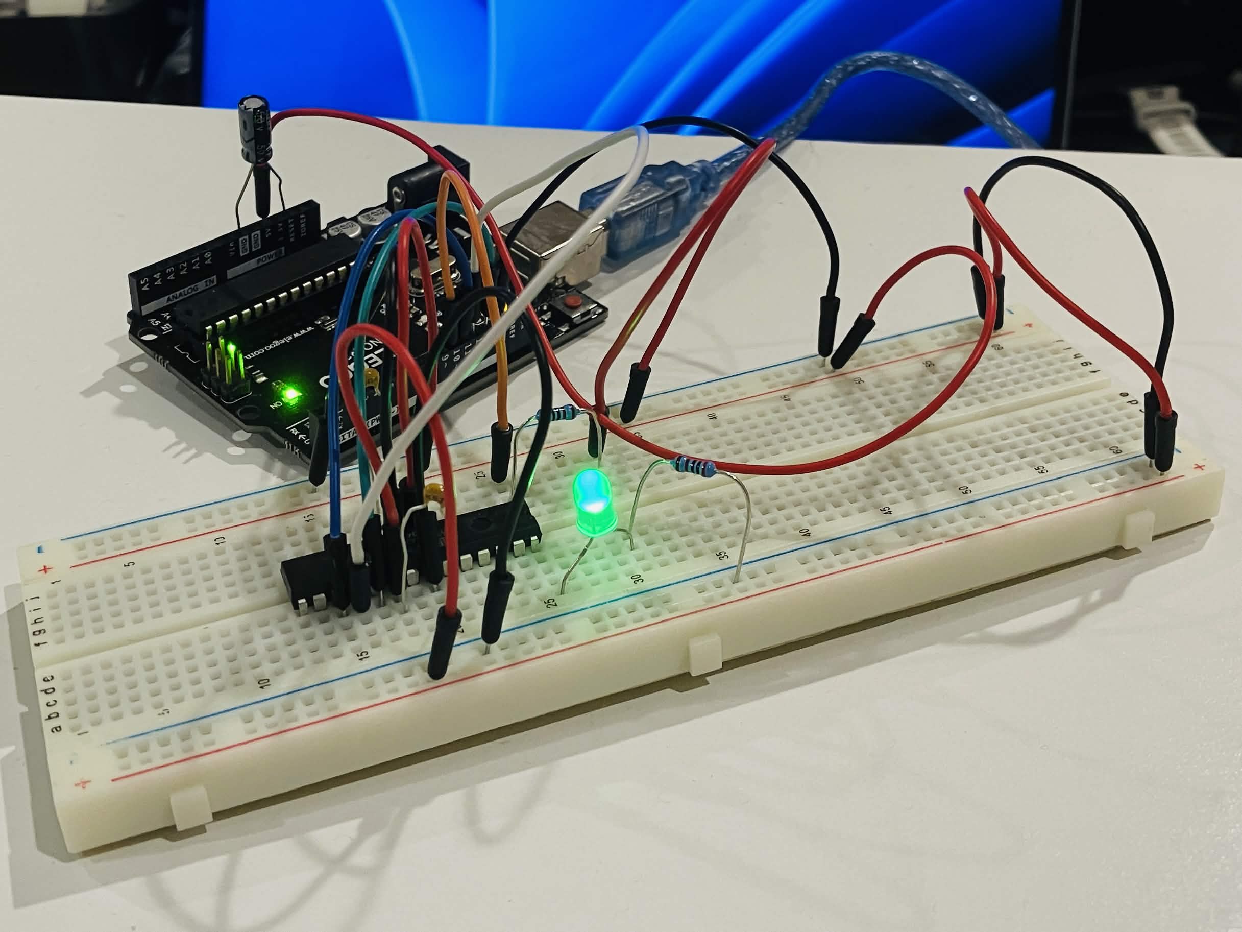
In today’s post, I program a microcontroller to make an LED blink.
Background
AVR ATMega328P
The AVR ATMega microcontroller series (now produced by Microchip Technology Inc.) is incredibly popular across hobbyist applications, primarily because it’s easy to program. The ATMega328P variant is especially popular as a MCU for the Arduino Uno board.
Programming an MCU typically requires a dedicated “programmer” device between the computer and the chip, which must often be purchased separately. In a wonderful demonstration of how easy the AVR chips are to program, we will be repurposing a stock Arduino Uno as our programmer.
Credits
I initially followed this excellent YouTube tutorial by The Printable Watch, and the bulk of this blog post directly matches his methods. I have endeavored to add value by explaining each step in greater detail.
In addition, this project would not be possible without MCUDude’s MiniCore project, making it easy to bootload an Arduino core to AVR chips!
Process
Hardware
- 1x AVR ATMega328P chip of the through-hole breadboard-mounted variety
- 1x breadboard
- 1x Arduino Uno-compatible board to act as our programmer
- 1x USB programming cable for the Arduino board
- 2x 2-kΩ resistors (one to act as a pull-up resistor on our RESET pin, the other to prevent burning out the LED on our “Blink” example)
- 2x 100-nF ceramic capacitors as decouplers (to smooth out our MCU power supply)
- 13x (approx.) male-male breadboard jumper cables
- 1x LED in your favorite color :)
Astute readers will note that I omit an electrolytic capacitor used by The Printable Watch between two Arduino pins. In my testing, this capacitor was not necessary; online research suggests it can speed up the programmer by avoiding Arduino bootloader delays.
Software
- Arduino IDE (with a few addons we’ll get to later)
Configuring the Arduino as a programmer
Load the Arduino ISP sketch by navigating to File -> Examples -> Arduino ISP in the Arduino IDE: 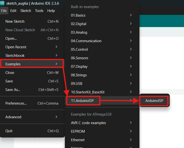
Upload the sketch to your Uno. Now your Arduino is configured as an in-circuit programmer! For more details on what that means, see the ArduinoISP example documentation!
Wiring the microcontroller
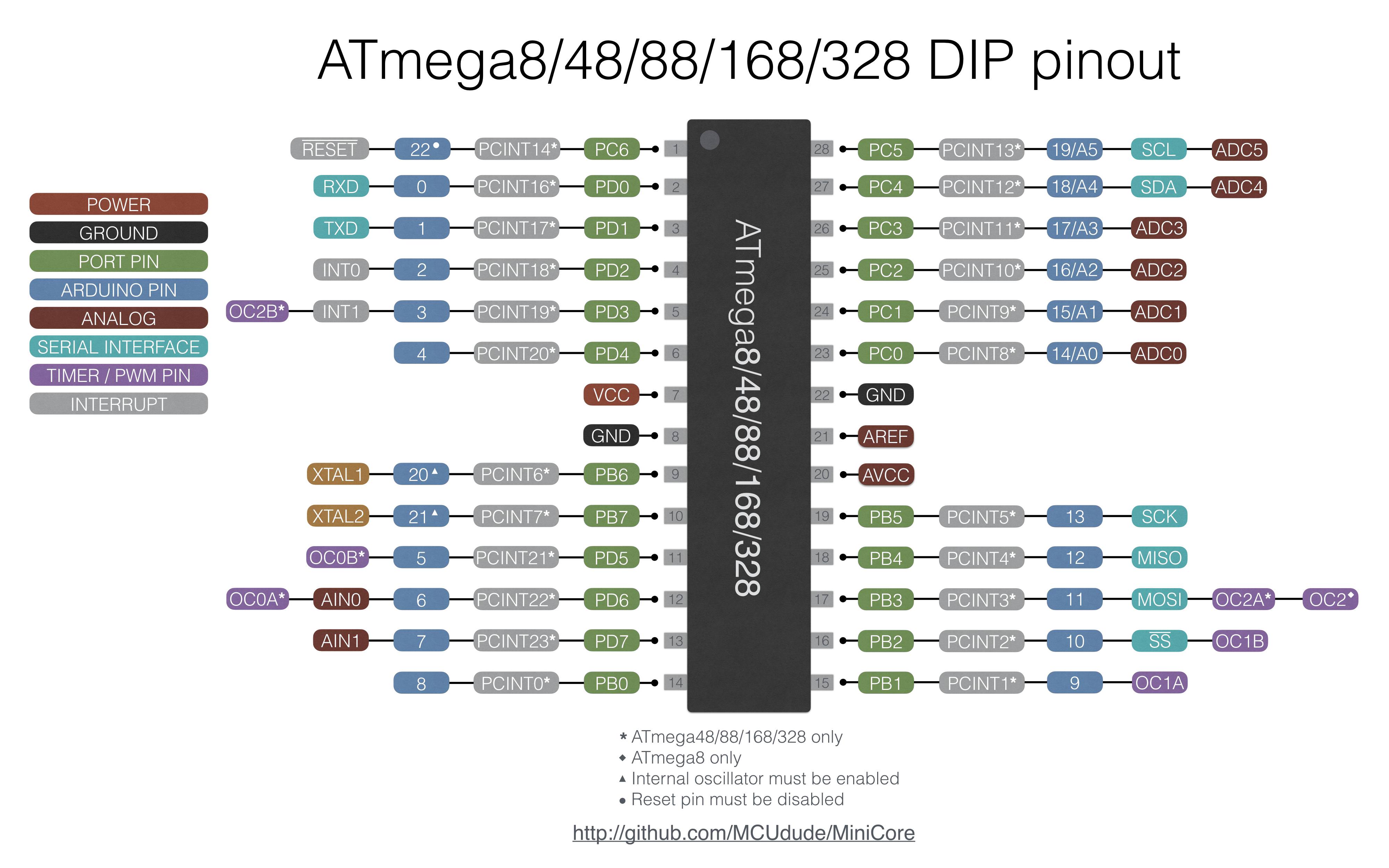
This section will reference specific pins on the microcontroller. It’s useful to review the datasheet, which contains pinouts like the following image, alongside a wealth of other useful information: 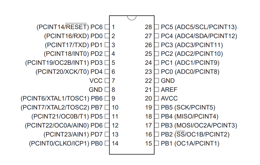
First, put the ATMega chip on the breadboard:
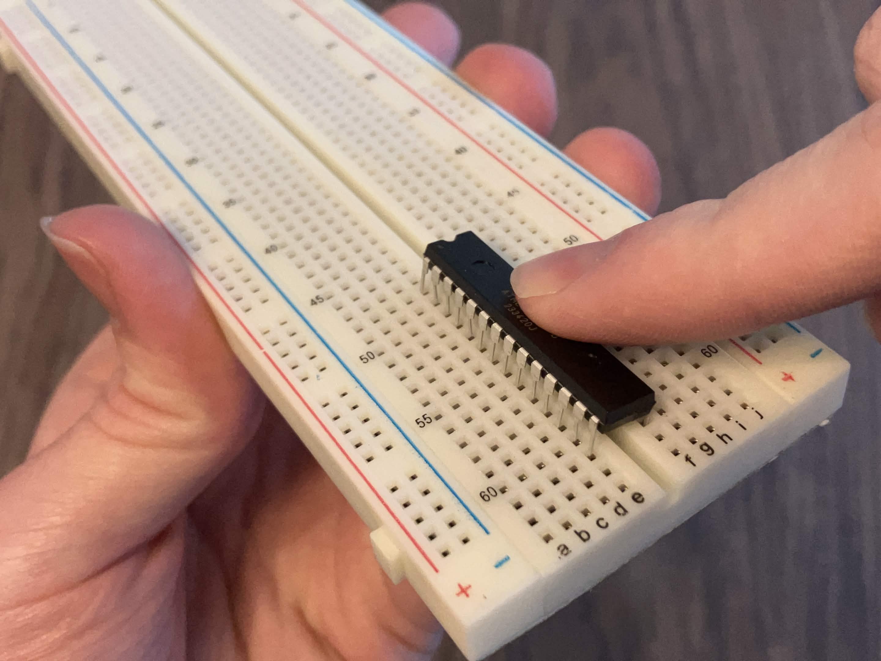
Next, bridge the +5V and ground rails on each side of the breadboard:
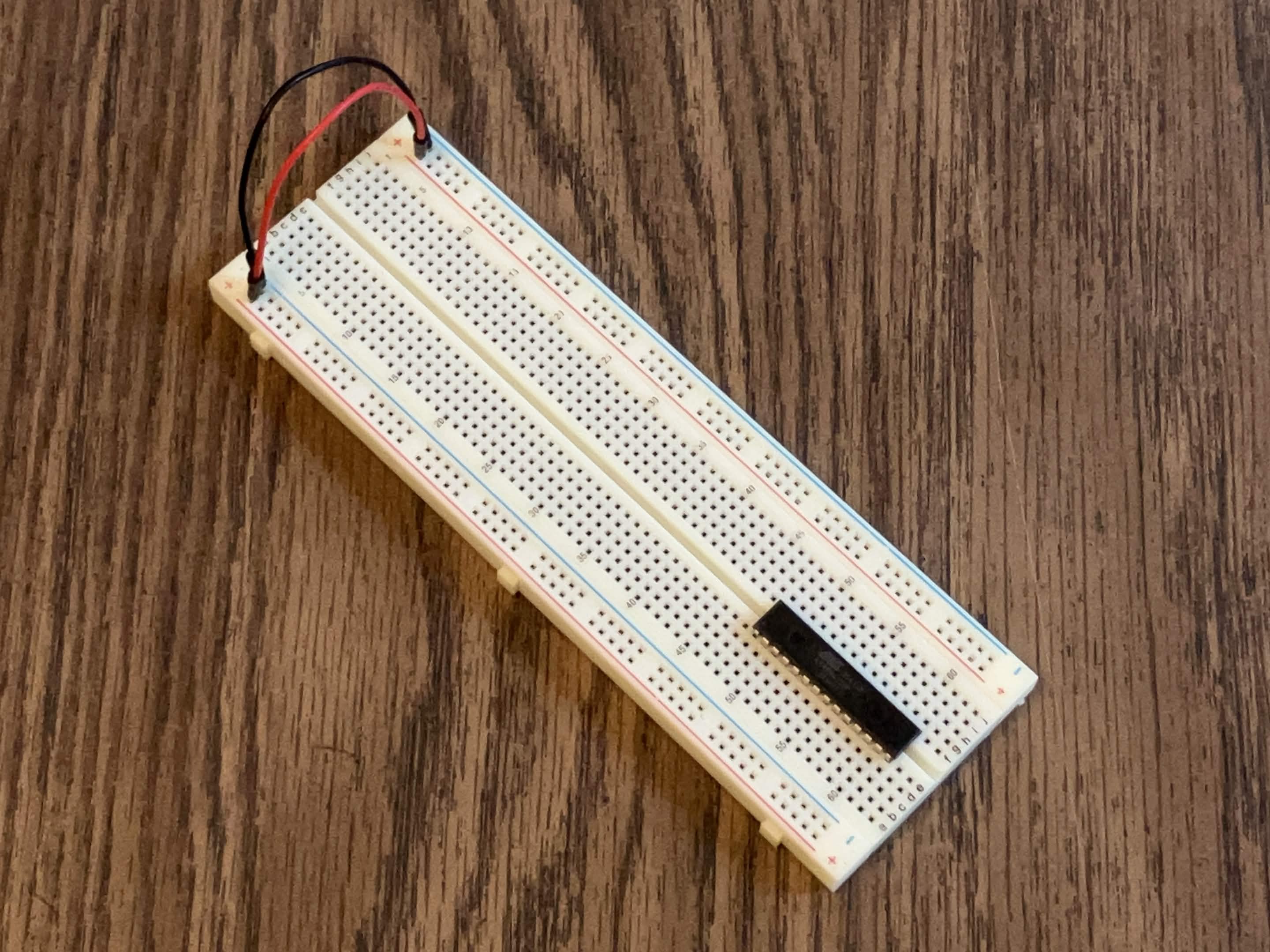
Connect the GND (ground) pins to the ground rail:
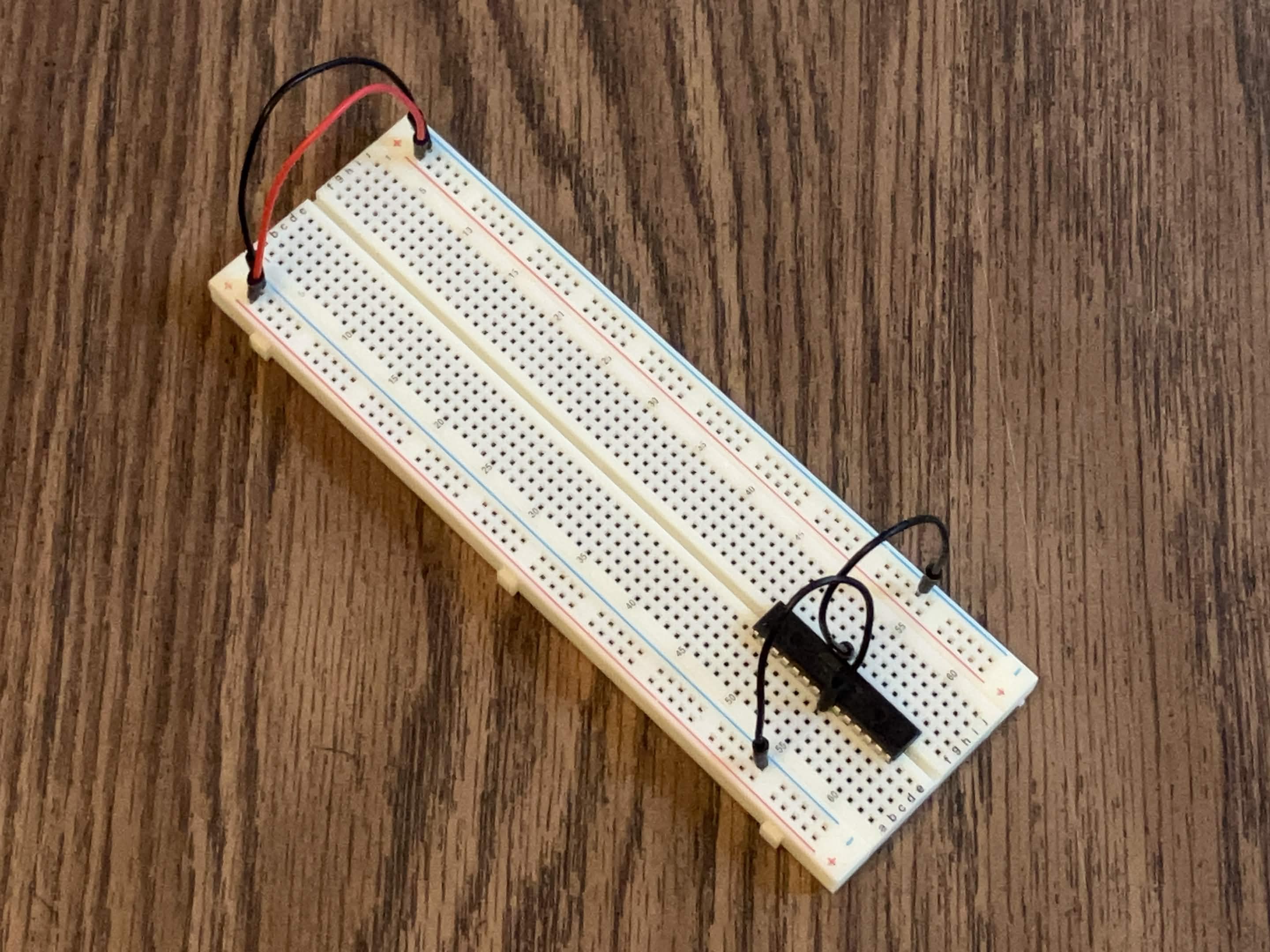
Connect the VCC and AVCC pins to the +5V rail:
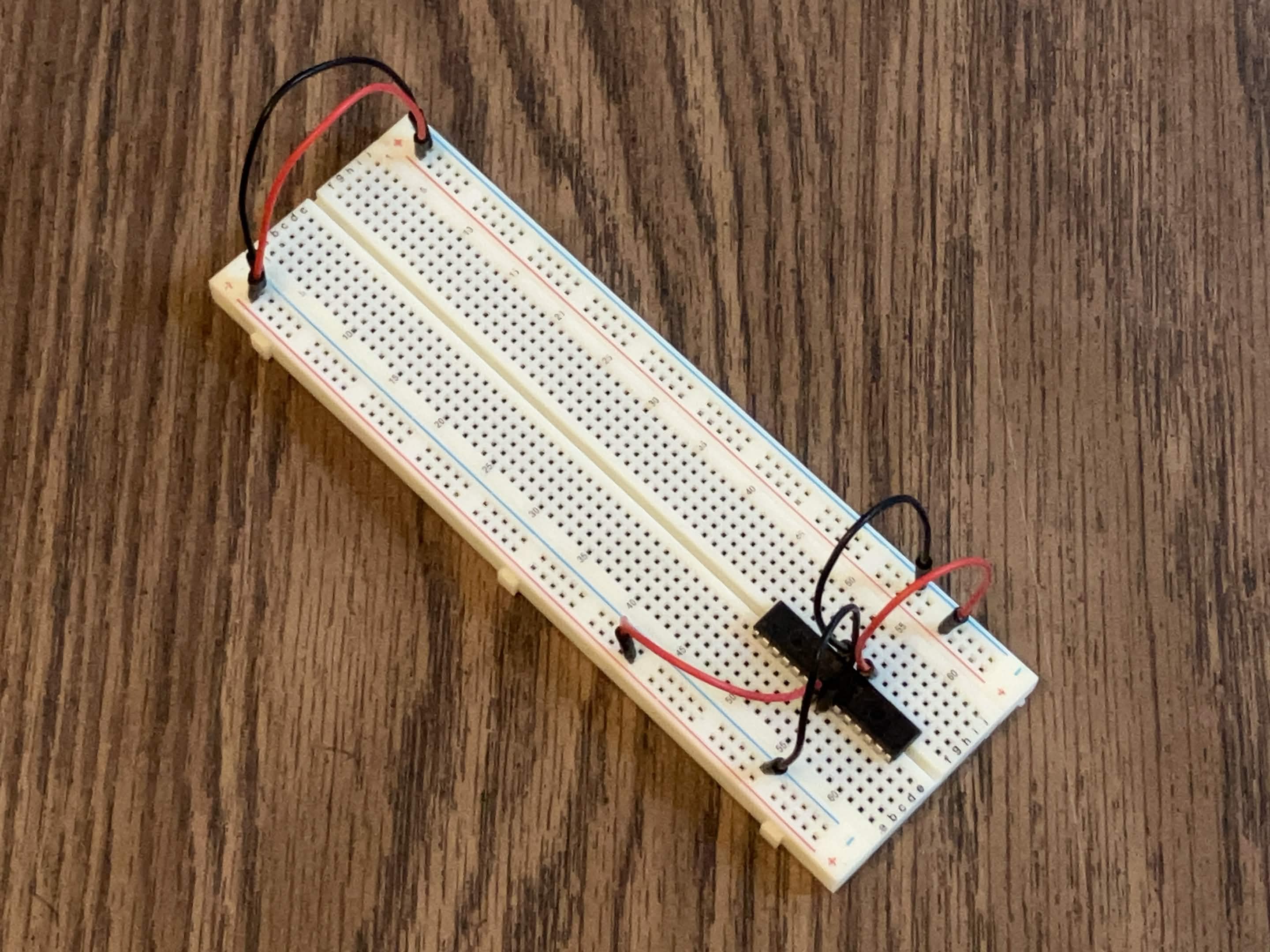
Add 100nF decoupling capacitors between each VCC/AVCC pin and the nearest ground pin, a pull-up resistor bridging the RESET pin to the 5V rail, and finally, an LED on pin 28, bridged to ground through a 2 kΩ resistor to avoid burning anything out.
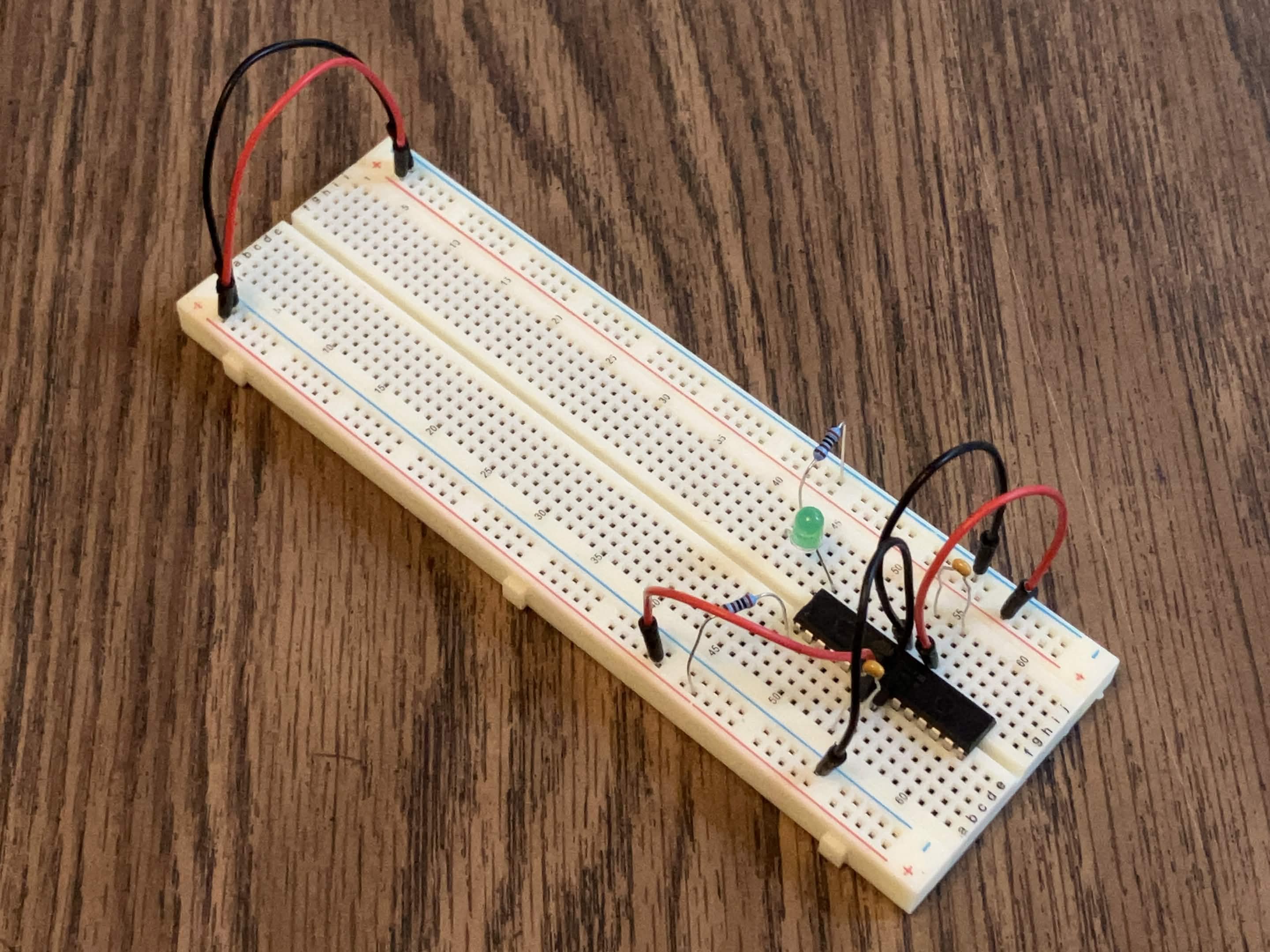
Since they store charge over time, capacitors resist changes in voltage. We use this property to smooth out power source irregularities with “decoupling” capacitors, typically one 100nF capacitor per VCC pin. To maximize effectiveness, these should be placed close to the pins they’re decoupling.
Pull up resistors (where the resistor bridges the pin to VCC) read “HIGH” when the pin isn’t powered and “LOW” when it is. Why would we want this? Well, according to the datasheet, port PC6 (RESET) will trigger a chip reset if it receives a “LOW” signal for greater than 2.5 microseconds. Our Arduino programmer will use this to reset the chip as necessary.
Wiring the two together
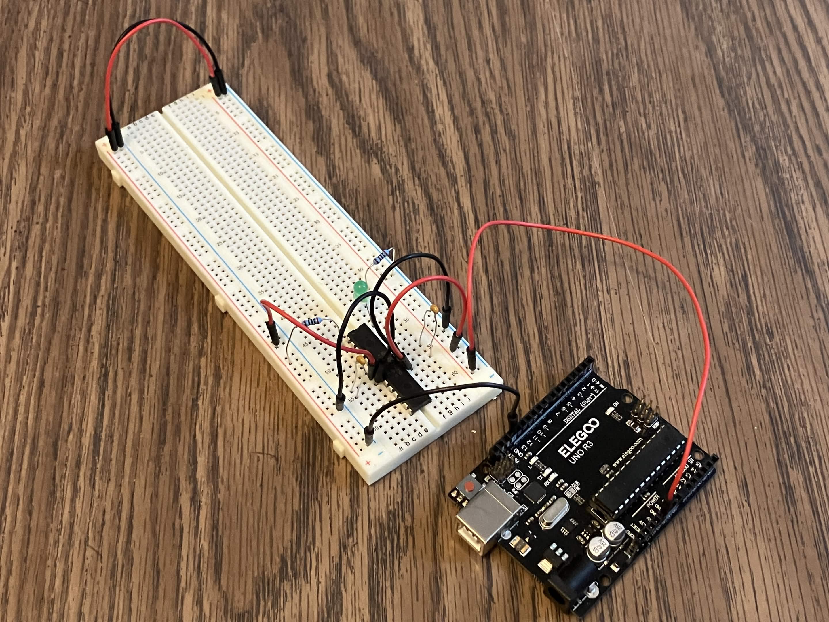
Connect the Arduino’s +5V and GND pins to the breadboard’s power rails:
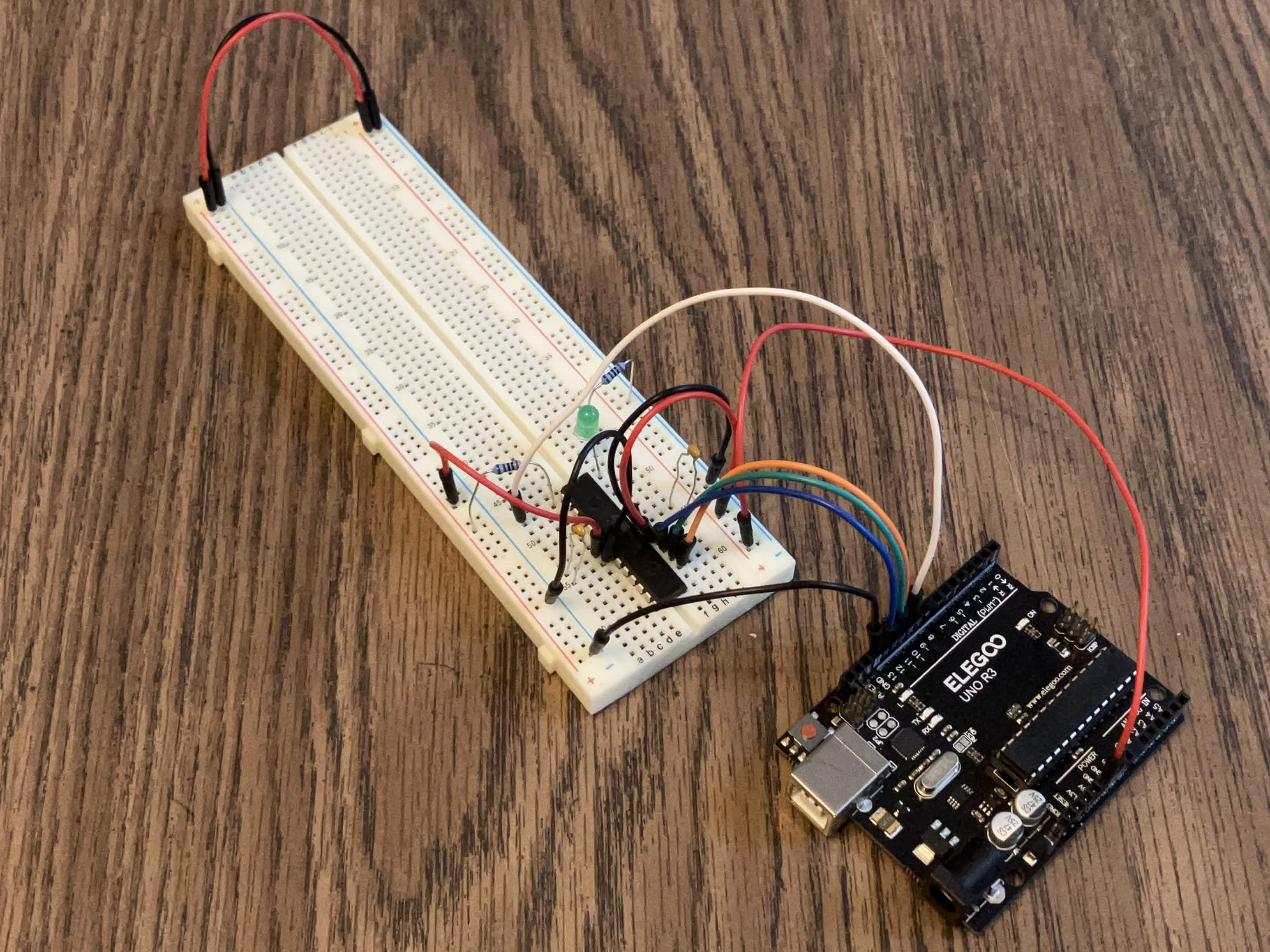
Consulting the AVR ATMega328p datasheet, connect the SCK, MISO, MOSI, and RESET pins we’ll use to program it:
Loading the bootloader
Burning the bootloader sets certain options necessary to specify which oscillator to use, brown-out settings, and a host of other options.
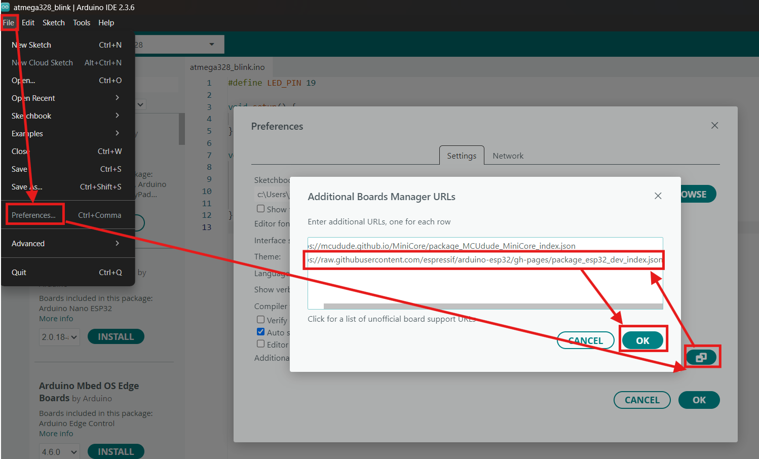
First, we’ll need to add the AVR board as an option in the Arduino IDE, by downloading it through the IDE from the following link:
https://mcudude.github.io/MiniCore/package_MCUdude_MiniCore_index.json
Browse to the library manager and use the above URL to install the board:
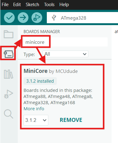
Then, search it up under boards, and install it:
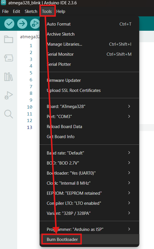
Finally, connect the programmer Arduino and navigate to Tools -> Burn Bootloader, ensuring that it is set to use the internal 8MHz oscillator!
Loading the “Blink” sketch
Pin mapping
Note that datasheet pins do not correspond to Arduino pins.
Our LED’s pin - pin 28 on the datasheet - corresponds to pin PC5, which translates to Arduino pin 19. See the following image, courtesy of MCUDude, for a helpful guide:
Modified “Blink” sketch
#define LED_PIN 19

void setup() {
  pinMode(LED_PIN, OUTPUT);
}

void loop() {
  digitalWrite(LED_PIN, HIGH);
  delay(1000);
  digitalWrite(LED_PIN, LOW);
  delay(1000);
}
To burn it to the AVR chip, use Sketch -> Upload Using Programmer.
Now you should have a blinking LED :] You can even remove the programming wires (RESET, MISO, MOSI, SCK) and leave the AVR chip just running off the Arduino’s power!
Next steps
You could add an external oscillator, integrate the AVR chip onto a PCB, or add another power method - for example, screw terminals with voltage regulators.
Thanks for reading!