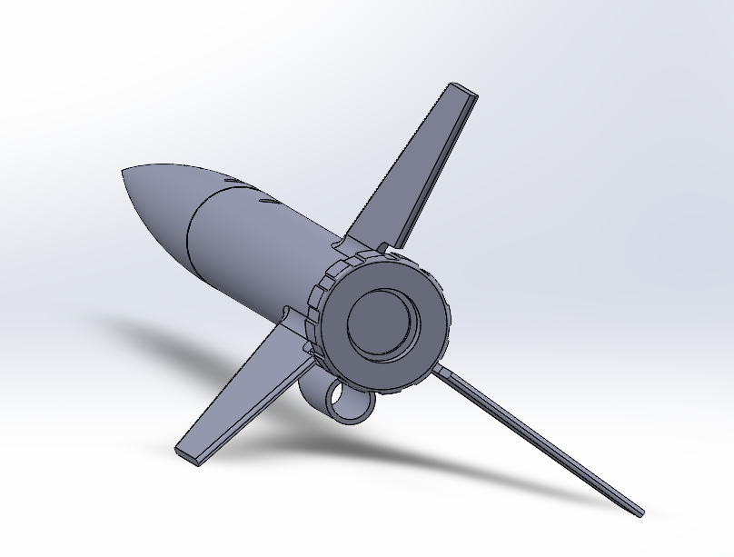
In today’s post, I share design details from my university rocketry club’s Flight Day rocket kits.
Printable Files
A comprehensive zipfile containing SolidWorks files, STEP files, and an OpenRocket file!
Background
Flight Day
One of my favorites from my university high power rocketry club was “Flight Day”, an annual event where we design and manufacture dozens of kits for ordinary students to assemble, decorate, and launch on campus!
Our first year of operation was a success, but our kits were plagued by a few issues, namely:
- Breaking on recovery (mostly due to launching on asphalt, but also due to our brittle PLA fins)
- A complicated single-use design
- Intensive kit setup and assembly, requiring a number of student mentors
- Parachutes made from plastic tablecloths and thread, which almost invariably failed to deploy or got tangled.
We tested several concepts to improve the kit for our second year, ranging from evolutionary to revolutionary. My own concept went through several iterations and test flights before the event.
Design Constraints
Apogee Requirements
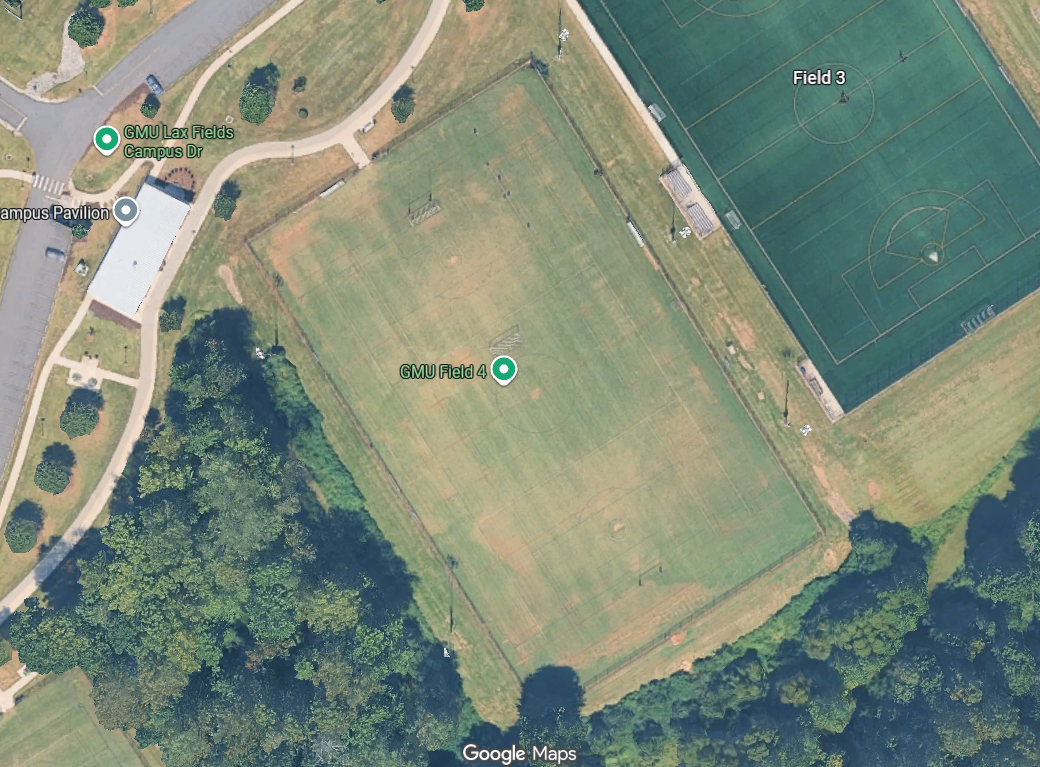
When designing a model rocket, the intended launch site is often a major constraint. This year, we were able to upgrade from a parking lot and reserve a soccer field, but we still need to avoid obstructions. A typical rule of thumb is to have half the rocket’s expected apogee clear of obstructions. We determined this would limit our flight ceiling to about 400 feet.
Recovery Requirements
Even with the half-apogee rule cleared of obstructions, there will still be spectators within the flight radius. This, combined with a desire to preserve the rocket, means we need to be very careful about recovery. The rule of thumb here is to aim for a ground impact velocity between 20 and 30 feet per second.
Most rockets use parachutes, but small rockets can also get away with streamers. With these, the critical safety aspect is that the rocket isn’t coming in ballistic; a tumbling recovery, is, for some very light rockets, sufficient.
Stability Requirements
To ensure the rocket goes straight up on launch (and not towards any spectators), it’s important that it be stable. Rocket stability is a complicated subject beyond the scope of this article, but the gist is that the rocket needs enough restoring moment to correct any disturbances. This requires:
- Enough distance between the center of pressure where aeroforces act, and the center of mass around which the rocket rotates, and
- Enough force acting on the center of pressure due to airspeed.
The rules of thumb in this regard are:
- At least one body diameter or at least 10% of the body length of distance between the center of pressure and the center of mass (whichever is greater), and
- A velocity of at least 50 feet per second off the launch rod.
Some rockets meet the first rule by adding a great deal of nose weight. This is often a fallacy, because it means less emphasis is placed on actual fin surface area for restoring forces to act upon. Like most rocketry rules of thumb, these work best with rockets of “normal” proportions.
Launch Requirements
Model rockets need a guided trajectory until they reach a stable speed. For small rockets at our scale, this is typically achieved with a launch rod that slips through a “launch lug” on the fuselage. From the previous Flight Day, we possessed a 1/8” sectional 1-meter launch rod, but had just taken generous delivery of a 1/4” 1-meter launch rod from one Prof. King. This meant that our rocket needed to be compatible with both launch rod diameters.
Construction Requirements
Within the scope of our event, the kits also needed to be:
- Mass producible with minimal setup labor;
- Capable of assembly within 15-20 minutes by a random college student;
- Cheap enough to produce dozens with or without university assistance.
Final Design
Propulsion
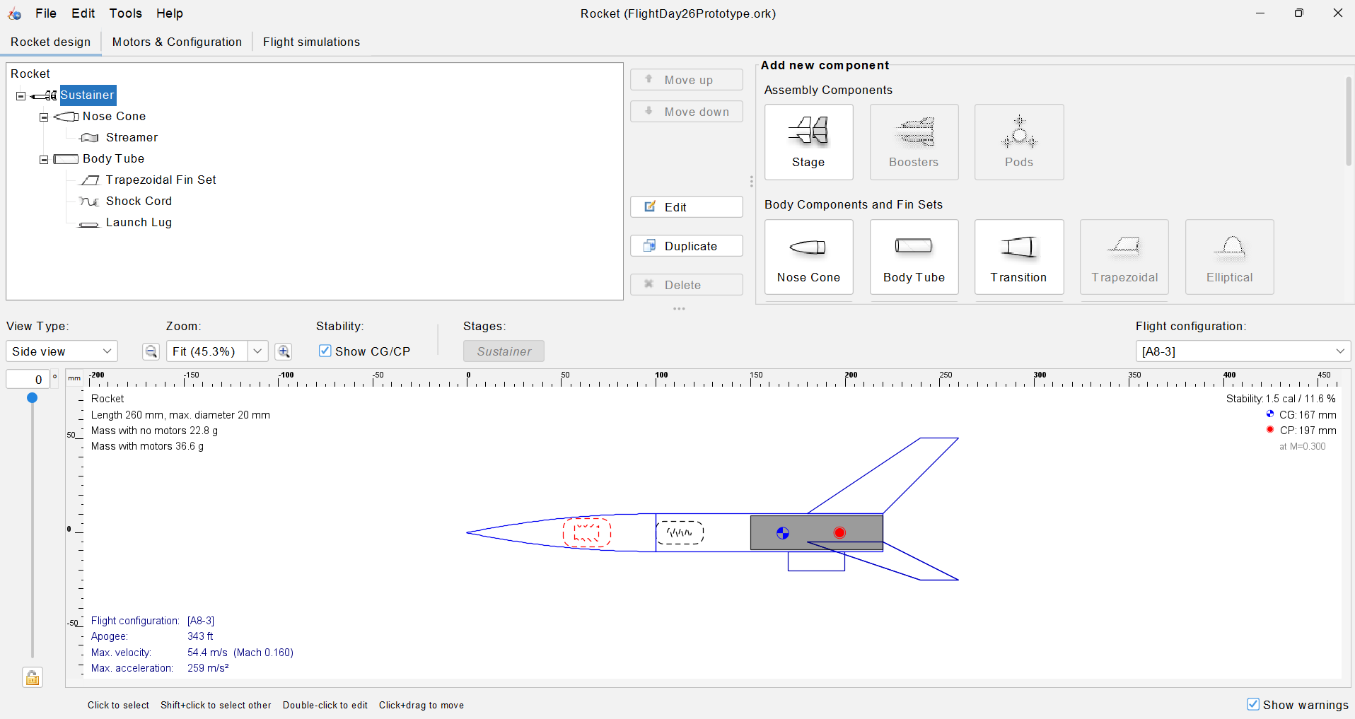
Estes A8-3 motors were a foregone conclusion for propulsion, since we had purchased multiple bulk packs the year before and had plenty left over. These motors conveniently include an ejection charge to deploy a parachute three seconds after engine burnout - making that duration my target for reaching apogee.
Airframe
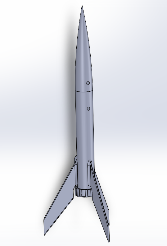
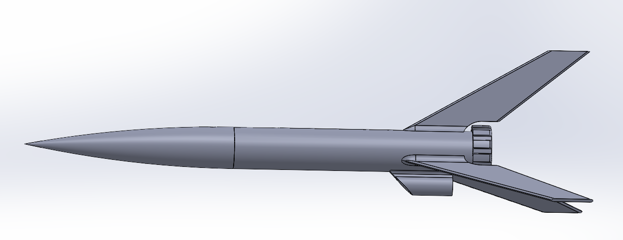
Based on our target motor, I created a design in OpenRocket which would not violate our 400’ altitude ceiling. It is a minimum-diameter design, using a screw-on motor retainer to prevent the motor from ejecting itself out of the rocket body.
Recovery
Once again targeting minimum cost, an approximately 6x20” streamer was cut from a plastic disposable tablecloth. We applied a small piece of electrical tape applied to one end, through which a hole was cut and the shock cord fed through. “Dog barf” (cellulose insulation) would be eventually packed between the motor and streamer to prevent the hot ejection gases from charring our recovery system.
Materials
PETG was selected as the filament of choice, due to its availability and higher melting point than PLA. The “shock cord” attaching the body to nosecone was a rubber band (for absolute minimum cost), secured on either end with electrical tape.
Manufacturing
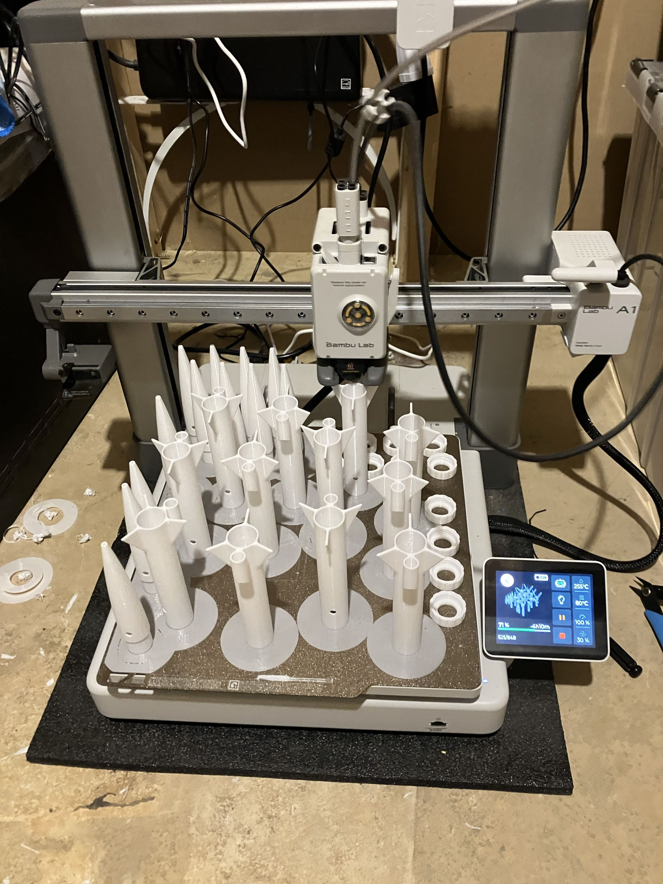
The simple, almost-entirely-3D-printed design proved easy to manufacture, which was a blessing, as the final design touches were completed about a day before the event. My Bambu Labs A1 worked overtime to print all the kits.
Flights
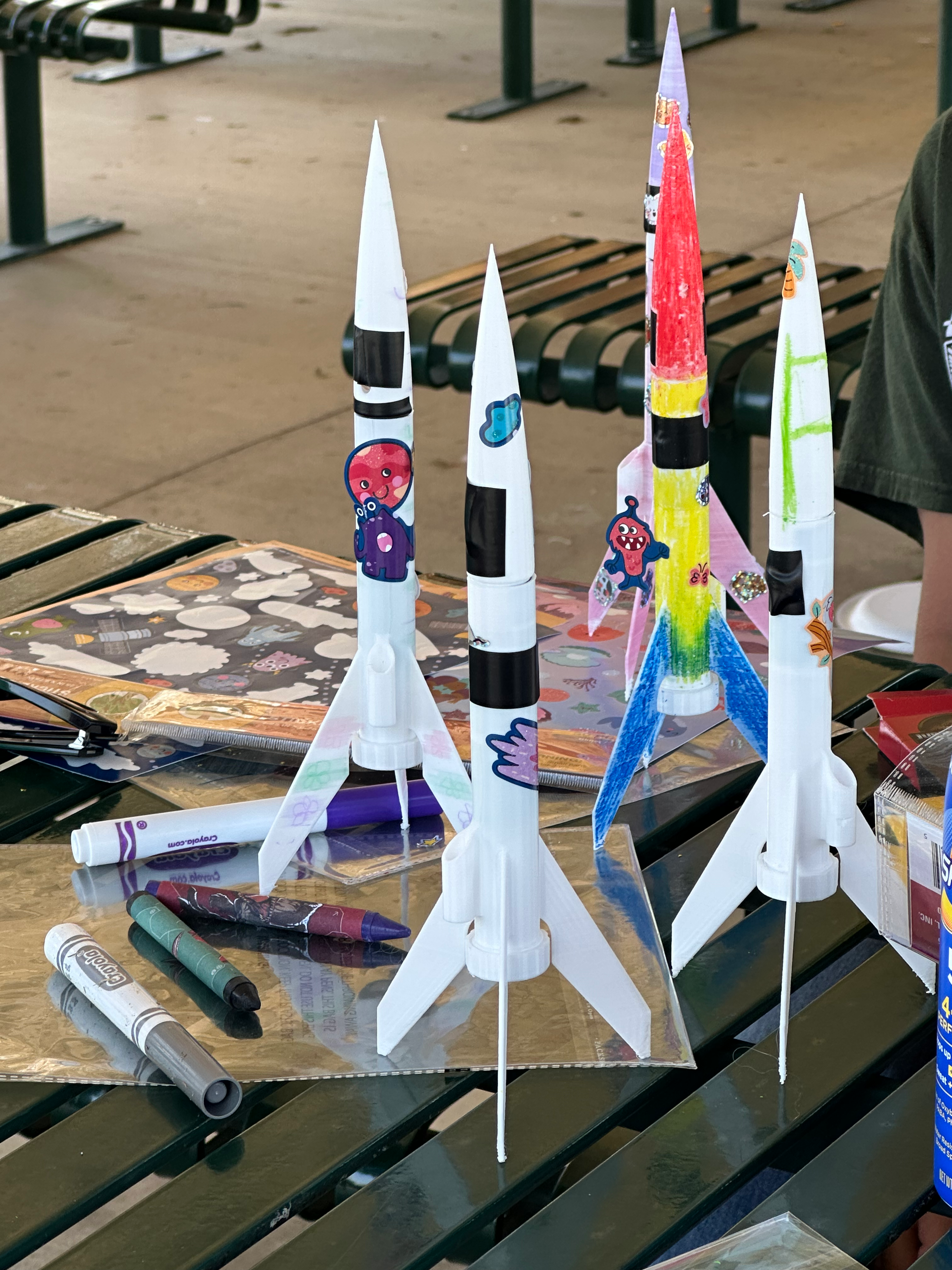
Though exact records weren’t kept, we flew between 20 and 30 rockets based on consumable usage. We ran out of igniters before we ran out of either kits or motors, and have a wealth of other supplies left over for next year :)
Next steps
At under $5 per launch (including motors and igniters), I’m pretty happy with the design as an absolutely minimal kit build. It could be improved in several ways, including:
- Improving the tolerances of the screw retainer, so that it doesn’t bite as much.
- Using a longer launch rod (some rockets were still a little unstable off the rod).
- Switching to a less finicky shock cord material and attachment method.
Thanks for reading!