In today’s post, I use a STM32C011J6M6 microchip to make an LED blink.
Background
While I was previously successful in programming ATMega chips, those chips are often relegated to purely hobby use. Serious embedded applications use more modern MCUs, such as STM32 chips. STM32 chips typically use an ARM architecture, are 32-bit (as the name suggests), and are often both cheaper and FAR more powerful than hobby options.
That said, they aren’t as aimed at hobby applications; through-hole versions typically aren’t available (hence my adapter PCB) and programming them involves more work.
Hardware
- 1x STM32C011J6M6 chip soldered to an SOIC-to-DIP breakout board (see my previous posts for how to design one yourself!)
- 1x breadboard
- 1x ST-Link programmer
- 1x 100nF capacitor for power supply decoupling
- 8x assorted DuPont male-male wires
- 1x LED of your favorite color :)
- 1x resistor of a “reasonable” value for the LED (200 Ohm, 2kOhm, it doesn’t matter too much)
Software
- STM32CubeMX to configure the MCU
- STM32CubeIDE to actually program it
Process
Wiring the MCU
VITAL NOTE: PA0 and PB7 are SWITCHED on the silkscreen I created for my breakout board. My wiring is correct, just ignore the text on the PCB.
In the course of these steps, it’s handy to have the datasheet pulled up. I find it useful to print out the page with the relevant pinout.
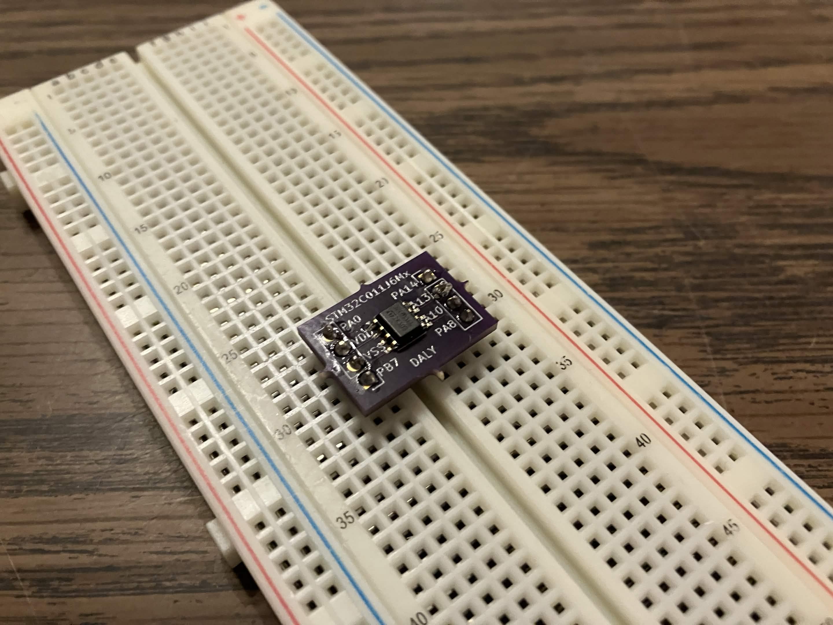
Insert the breakout board into the breadboard:
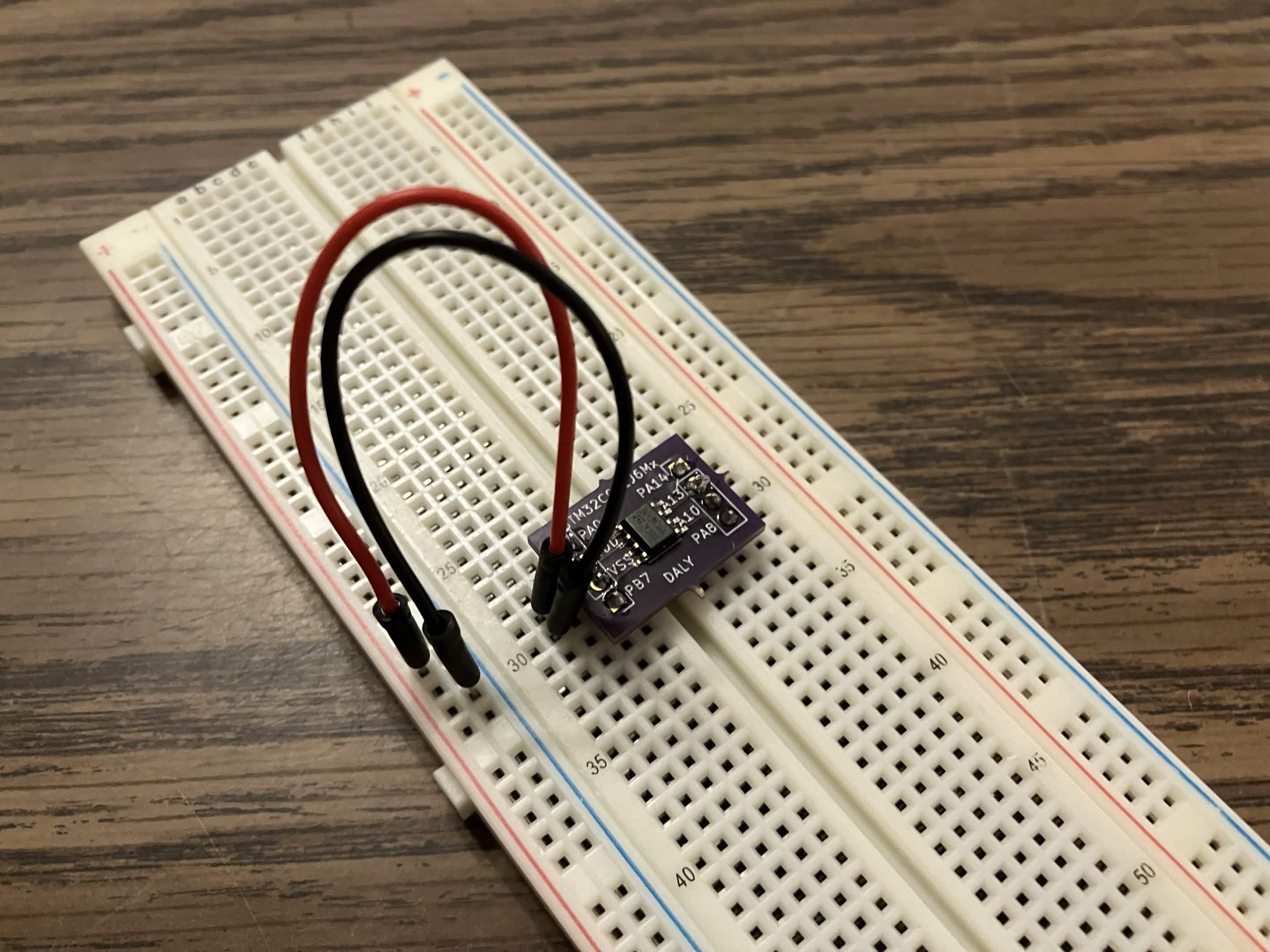
Connect VSS to ground and VDD to +3.3V:
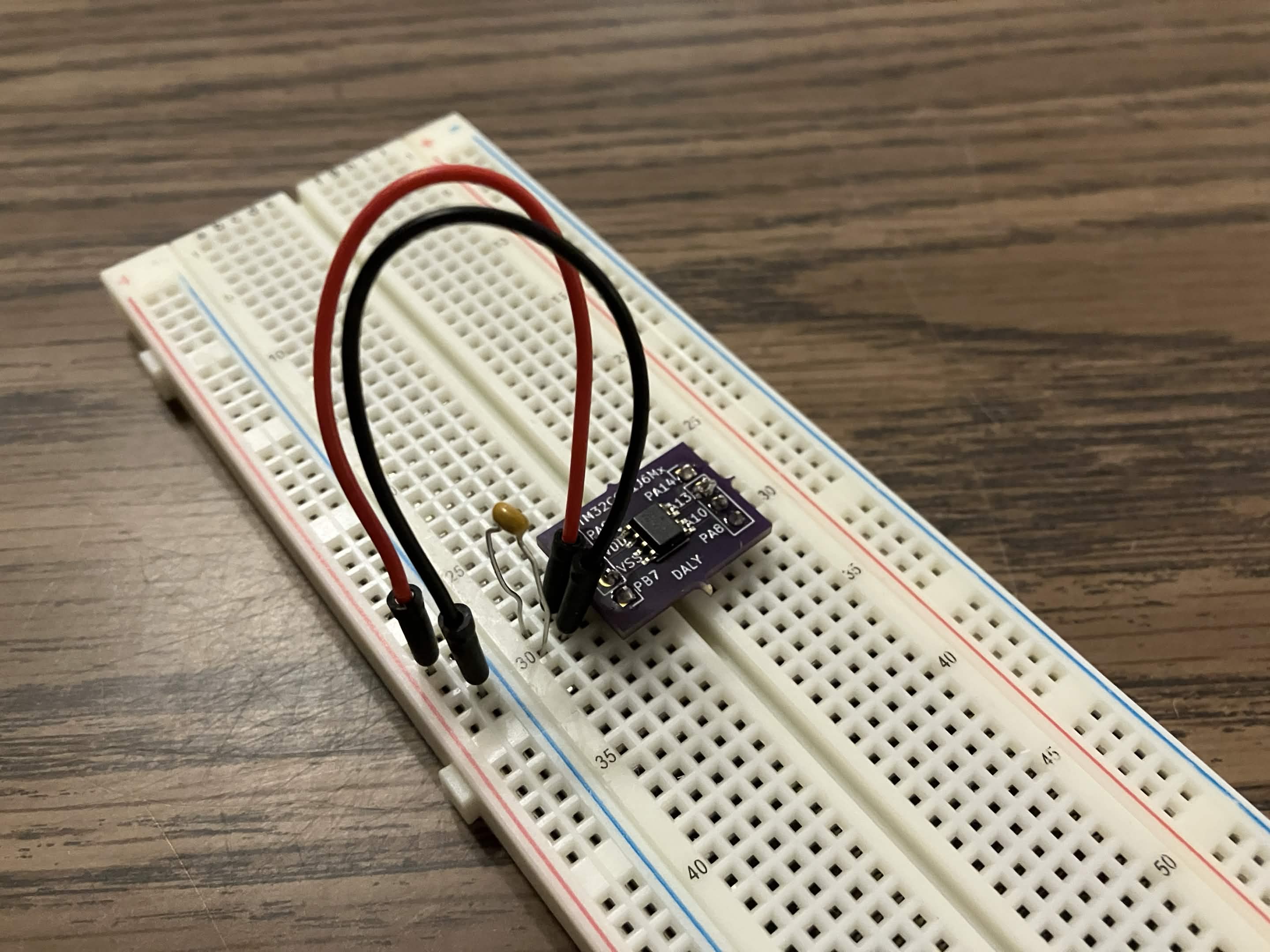
As usual, a decoupling capacitor is next; 100nF between the VDD and VSS pins. This will help to smooth out any power draw irregularities.
Finally, connect an LED in series with a resistor to pin 1:
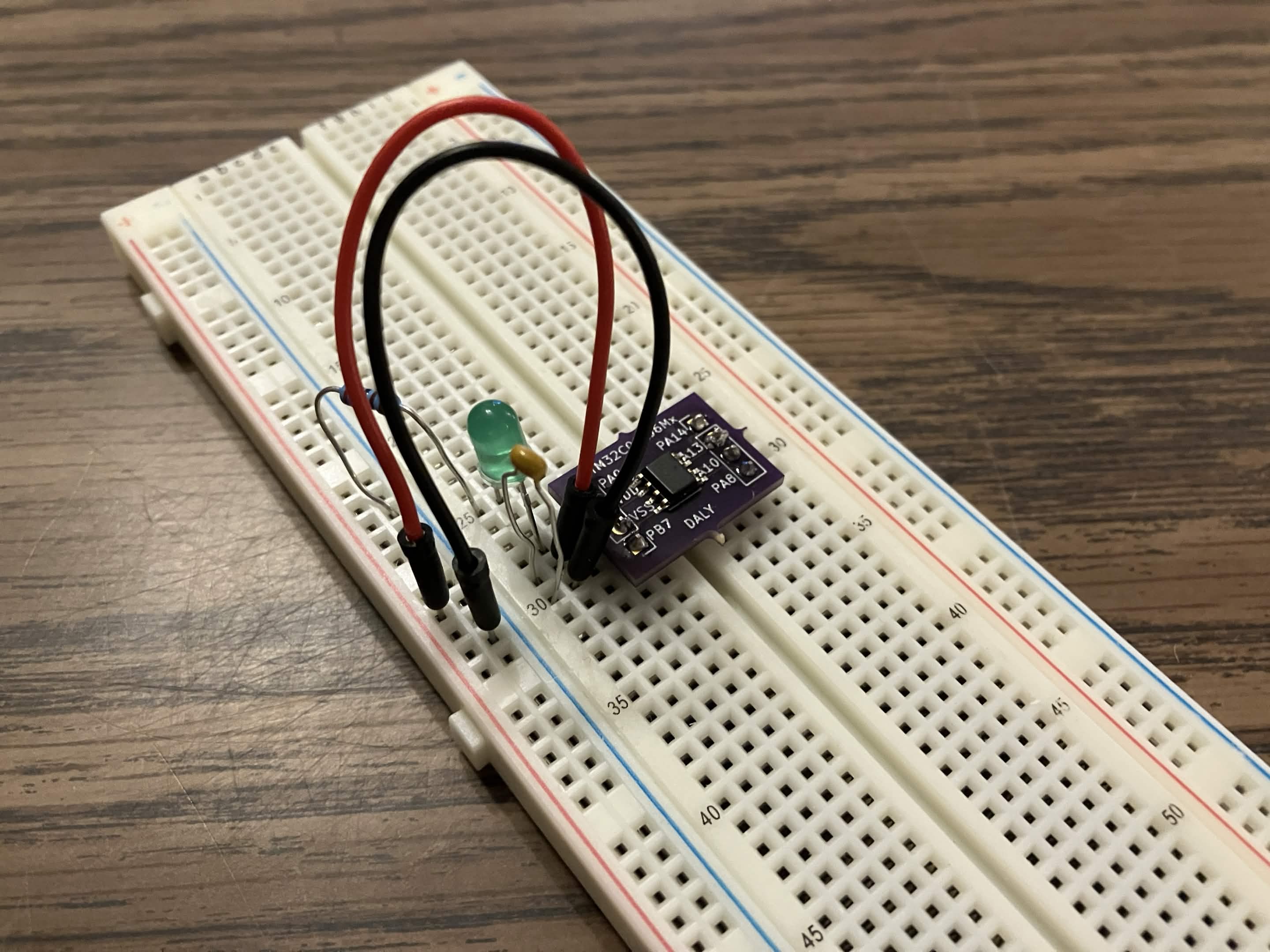
Barring the programmer, this is our entire setup. We will be using the MCU’s internal oscillator.
Configuring the MCU in STM32CubeMX
CubeMX is the standard interface for configuring STM32 boards. Once you’ve configured the board and pinout, it’ll transfer to the CubeIDE.
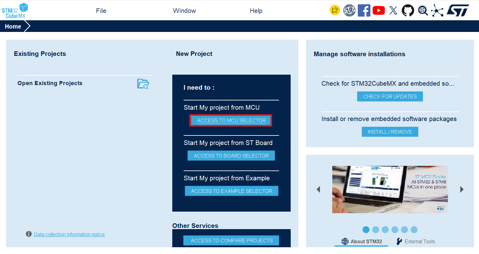
Open CubeMX and click “Start from MCU”:
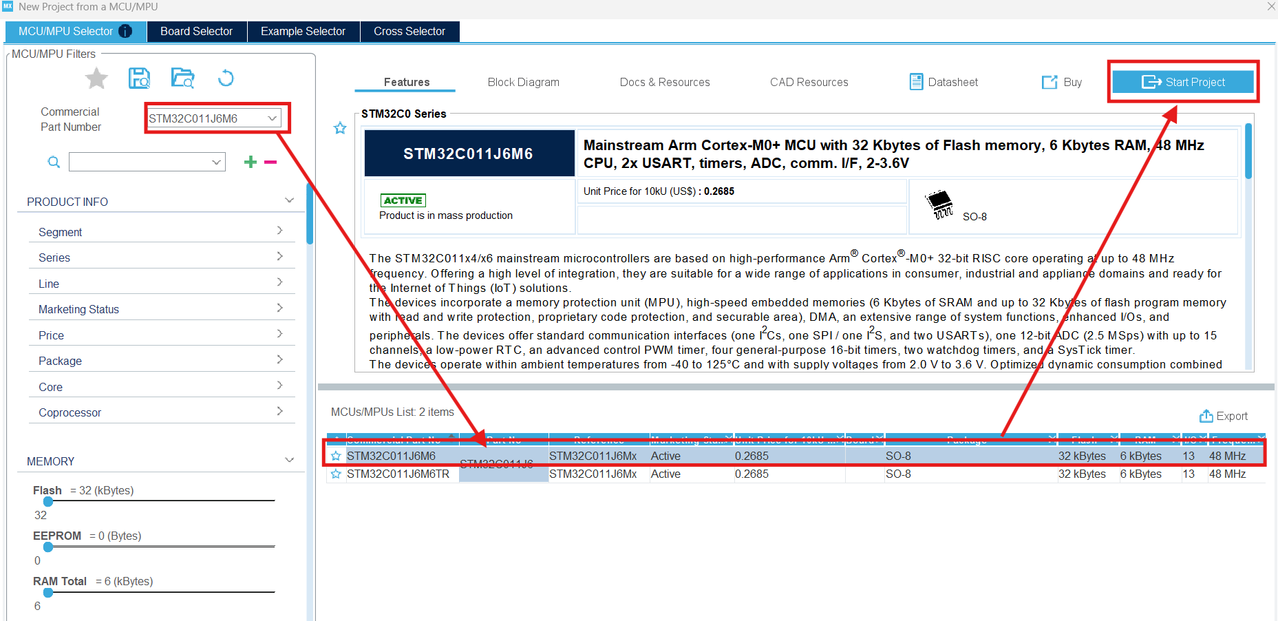
Select the STM32C011J6M6:
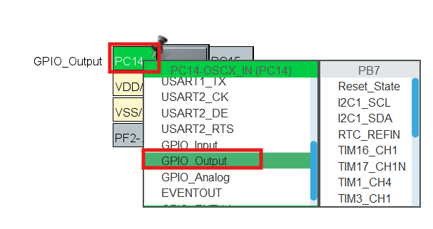
Set Pin 1 (PC14) to a GPIO (General Purpose Input/Output) Output. This will let us use the pin to send signals.
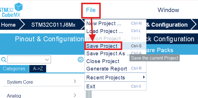
After much trial and error, I have discovered that it is critical the next three steps are executed in this exact order.
Set the save location of the CubeMX project to a directory of your choice:
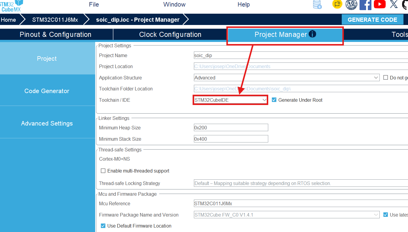
In the Project Manager, ensure the toolchain is set to “STM32CubeIDE”:
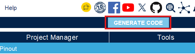
Finally, hit the “Generate Code” button!
Opening the project in STM32CubeIDE
Now the board is configured, and we’re ready to program. Open CubeIDE and import the CubeMX project:
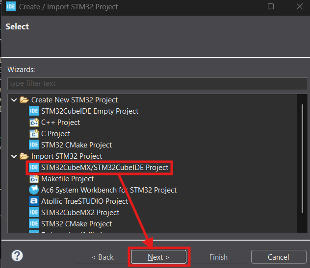
Select the directory you exported to from CubeMX.
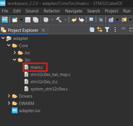
Next, open the main.c file:
Find the while(1) loop, and insert the following:
  /* USER CODE BEGIN WHILE */
  while (1)
  {
	  HAL_GPIO_TogglePin(GPIOC, GPIO_PIN_14);
	  HAL_Delay(1000);
  }
  /* USER CODE END 3 */
This will toggle our pin 1 (PC14) once every second.
Connecting the ST-LINK
Before we run the program, we need to connect the board. This is done with the ST-LINK programmer. If you have the small USB stick version of the ST-LINK, your pins will be different.
The following two images are directly reproduced from the ST-LINK V2 manual and are owned by ST:
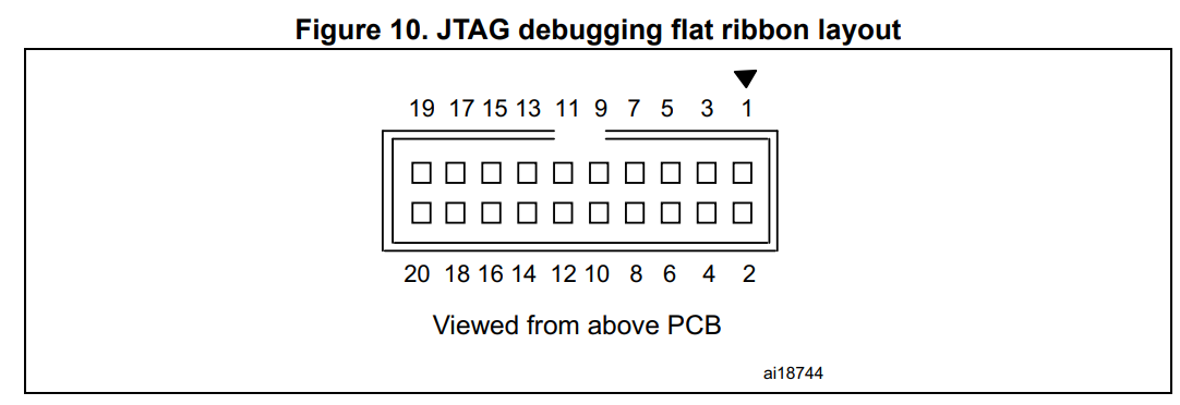
On the ST-LINK, the red stripe indicates pin 1.
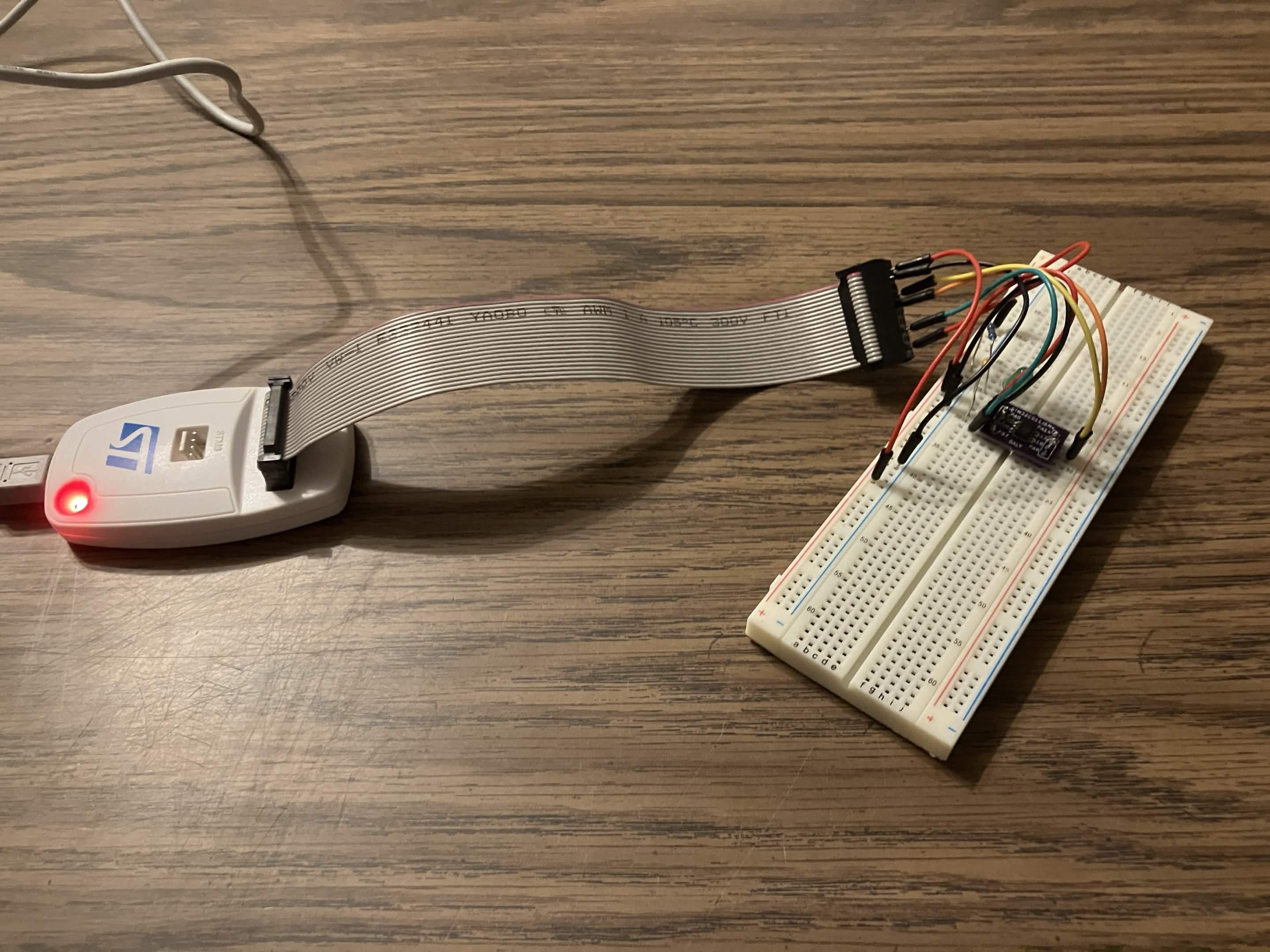
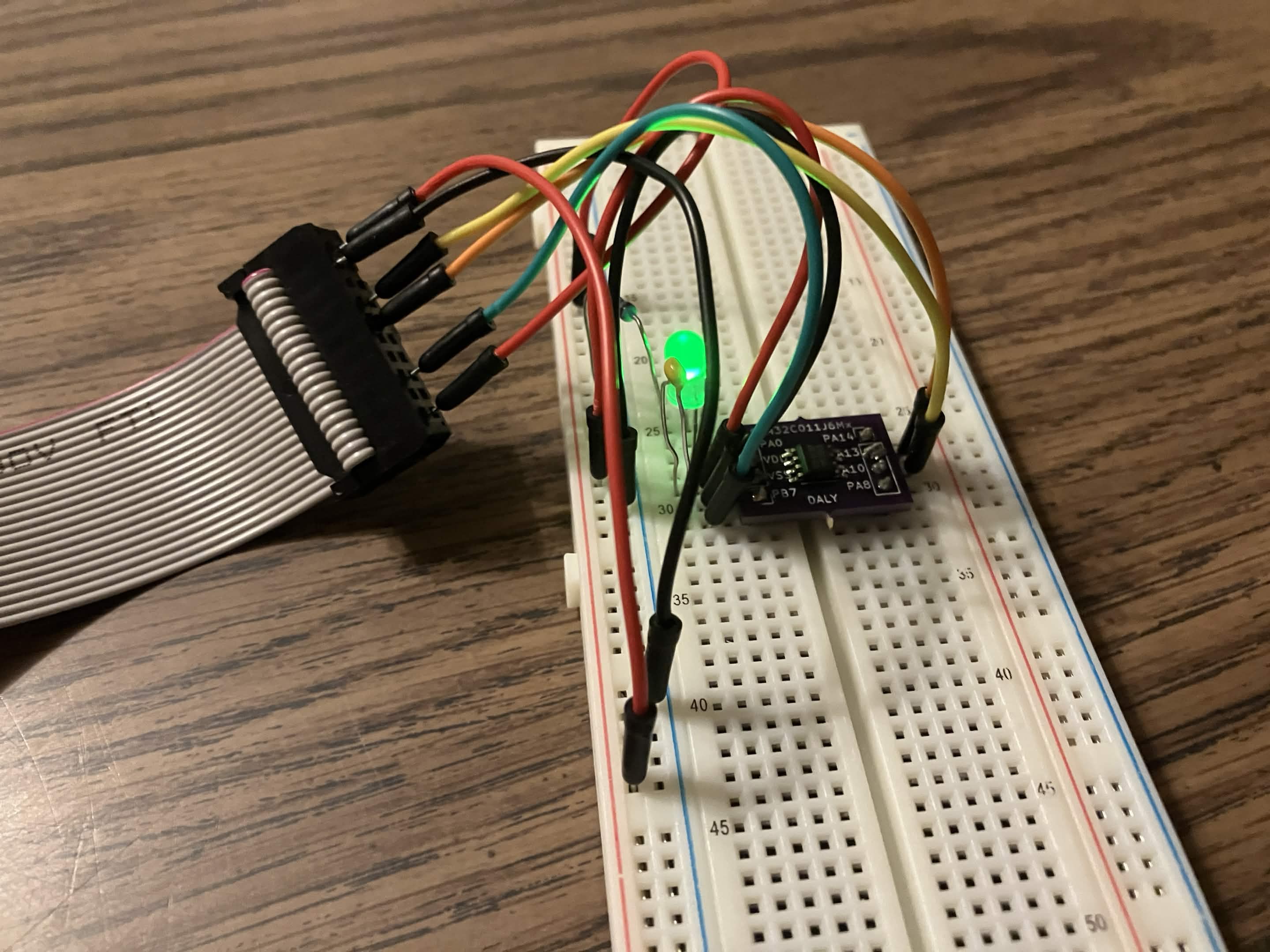
Connect the following ST-LINK pins to the requisite MCU pins:
- 1 (VAPP) and 19 (VDD) to the +3.3V breadboard rail
- 4 (GND) to the breadboard ground rail
- 7 (TMS_SWDIO) to pin 7 on the MCU (PA13)
- 9 (TCK_SWCLK) to pin 8 on the MCU (PA14)
- 15 (NRST) to pin 4 on the MCU (PA0)
Programming the MCU
With the ST-LINK connected over USB, hit “Debug”:
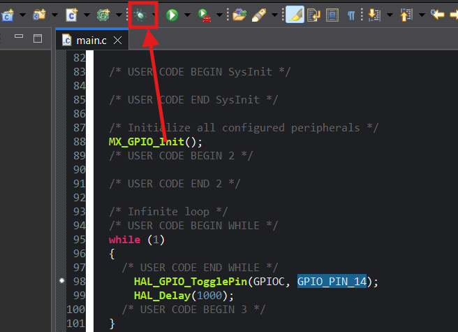
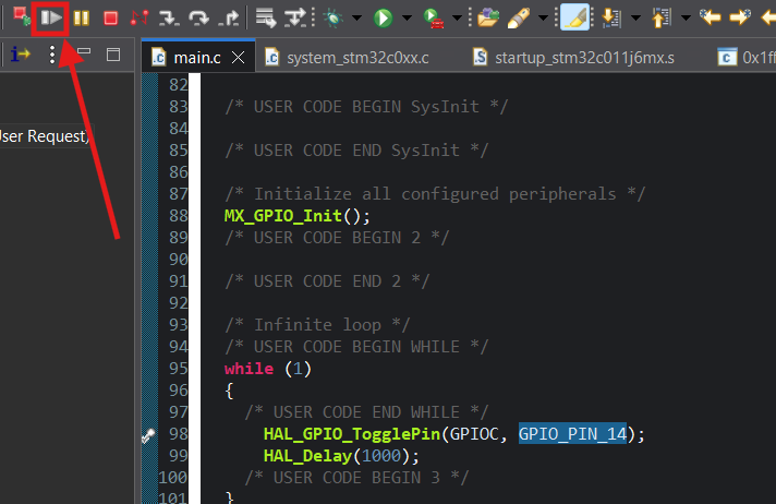
If all is well, the code will be uploaded, but nothing will happen just yet. The debugger has a breakpoint set early in program execution. Click the Resume button to proceed to your main loop.
Now your LED should be blinking!
If you get a build error, the issue is likely in your CubeMX project configuration. Ensure that your toolchain is set properly.
If you get an error from the ST-LINK, the issue is most likely with your wiring.
Next steps
The 8-pin SOIC format of the STM32C011J6M6, with its limited/shared GPIO pins, is fairly restrictive on applications. Improvements could include:
- Using a MCU with more GPIO pins
- Adding a power supply
- Integrating the decoupling capacitor onto the PCB
- Adding a USB connector, and turning the MCU into a proper development board
Thanks for reading!